Showing posts with label Networking. Show all posts

Thursday

Setting Up Windows For Our Network

Setup NetworkConfiguring our computers for our home computer networkAfter all the hardware for our home computer network has been setup , we now have to setup our computers to allow communication with each other. Though we have our hardware in place it remains useless unless the computer knows what to do with it, and it is you who has to tell it what to do with the hardware. In this article we will go through the process of setting up the software side of our network, which is not very complicated, actually a lot of it is automated or semi-automated where the computer does most of the work.

Some of the stuff you need to do is routine technical stuff like installing the drivers (software that controls the hardware devices like the NIC) on your computer. Also you will need to set up each computer so they are ready to share their files on your home network.

Note for Wireless Users: If you are using a wireless router on your network then you will need to install the router first. Though installation procedures vary among manufacturers, for the most part they all have the same general setup.

Drivers for hardware

Your network connectors, whether they be ISA, PCI or a USB connecter are all hardware devices which will need you to install little software programs known as drivers. Drivers help the operating system communicate with hardware, telling the hardware what to do and when to do it.

After you physically install the network adaptor on your computer, the next time you turn it on, windows should automatically discover it and request for a driver to be installed. This very cool feature in windows is known as plug and play, which goes to work while windows start up. The plug and play feature will want to install your hardware straight away and will request for you to provide the correct information for it to be installed properly.

With USB connectors you can plug the device into the computer while it is on and windows will automatically detect it for you and bring up the "add new hardware" wizard. This ability to install hardware whilst the computer is on is known as a hot installation (by techies), and its one of the coolest things about USB devices... Get it?... HOT installation... COOLEST thing about USB?

Come on that's funny!

Oh Never mind!

There are times the plug and play feature in windows will not detect your new hardware, in that case it will be up to you install the driver manually.

Protocols to start Communication

Now windows has the appropriate drivers to communicate with our network adaptors, it is time for our computers to start communicating . In order for our computers to communicate, they need to have the same network protocol (That's tech talk for the language computers use to communicate). There are two types of protocols used for computer to computer communication, TCP/IP or NetBEUI. Depending on your version of windows each one will be installed automatically. Windows XP installs TCP/IP automatically so if you wanted to use NetBEUI on XP you would have to install it using you windows CD, and vice versa if you were using windows 98.

Each computer must be installed with the same protocols in order to communicate; this installation binds the protocol and the network adaptor together. As soon as each computer can talk the same beautiful language, then services can begin on the network. Each task that you want to perform on a network, like file sharing, print sharing and logging on to the network is known as network services.

Naming computers and Work groups

There is one more task to do in order for our computers to communicate and share resources. The Microsoft Network system is very anal when it comes to networking rules and demands to know who's who, who's where and what's what. Because of this computers must be given a name (each one having to be unique, so you can't have two computers with the same name).

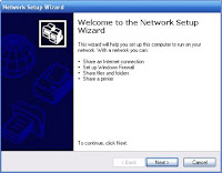
Also you must give each computer a work group (the group in which you network exists, so each computer must be in the same group) Windows Networking wizard If you are using Windows Me or XP you do not have to go through most of this, you can use windows home networking wizard to set it up for you.

The windows home networking wizard walks you through the process of setting up your network, it also sets up the shared internet connection for you. A lot of people do not like using this wizard because they say it complicates things (I can't say I am too fond of it my self). I would recommend you doing it all manually it helps you understand how windows works a lot better.

Share/Bookmark

Monday

WAN and Client Server Applications

WAN & Client Server
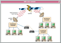
There is no denying the fact that the communications servers provide support for wide area network communications. This support typically includes support for a subset of IBM System Network Architecture, asynchronous protocols, X.25, ISDN, TCP/IP, OSI, and LAN-to-LAN NetBIOS communication protocols. In the Novell NetWare accomplishment, Gateway Communications make available a leading communications product. In the LAN Server and LAN Manager environments, OS/2 communications server products are available from IBM and DCA. In the Banyan VINES environment, the addition of DCA products to VINES provides support for SNA connectivity.

UNIX servers provide a range of product add-ons from various vendors to support the entire range of communications requirements. VMS servers support Decent, TCP/IP, and SNA as well as various asynchronous and serial communications protocols. MVS servers provide support for SNA, TCP/IP, and some support for other asynchronous communications. Security at the server restricts access to software and data accessed from the server. Communications access is controlled from the communications server. In most implementations, the use of a user login ID is the primary means of security. Using LAN Server, some organizations have implemented integrated Response Access/Control Facility security by creating profiles in the MVS environment and downloading those to the LAN server for domain control.

Systems and network management services for the local LAN are managed by a LAN administrator, but WAN services must be provided from some central location. Typically, remote LAN management is done from the central data center site by trained MIS personnel. The discussion in the following sections more specifically describes the functions provided by the server in a NOS environment. Requests are issued by a client to the NOS services software resident on the client machine. These services format the request into an appropriate RPC and issue the request to the application layer of the client protocol stack. This request is received by the application layer of the protocol stack on the server. File services handle access to the virtual directories and files located on the client workstation and to the server's permanent storage. These services are provided through the redirection software implemented as part of the client workstation operating environment.

In order to diminish the effort and effect of installation and maintenance of software, software should be loaded from the server for execution on the client. New versions can be updated on the server and made immediately available to all users. Furthermore, setting up in a central location reduces the effort required for each workstation user to knob the installation process. Because each client workstation user uses the same installation of the software, non-compulsory parameters are consistent, and remote help desk operators are aware of them. This simplifies the analysis that must occur to provide support. Sharing information, such as word processing documents, is easier when everyone is at the same release level and uses the same default setup within the software.

Central productivity services such as style sheets and macros can be set up for general use. Most personal productivity products do permit local parameters such as colors, default printers, and so forth to be set locally as well. Backups of the server can be scheduled and monitored by a trained support person. Backups of client workstations can be scheduled from the server, and data can be stored at the server to facilitate recovery. Tape or optical backup units are typically used for backup; these devices can readily provide support for many users. Having Placed the server and its backups in a secure location helps prevent theft or accidental destruction of backups.

A central location is readily monitored by a support person who ensures that the backup functions are completed. With more organizations looking at multimedia and image technology, large optical storage devices are most appropriately implemented as shared servers. High-quality printers, workstation-generated faxes, and plotters are natural candidates for support from a shared server. The server can accept input from many clients, queue it according to the priority of the request and handle it when the device is available. Many organizations realize substantial savings by enabling users to generate fax output from their workstations and queue it at a fax server for transmission when the communication costs are lower. Incoming faxes can be queued at the server and transmitted to the appropriate client either on receipt or on request.

In view of the above discussion it is evident that in concert with workfare management techniques, images can be created and disseminated to the suitable client workstation from the image server. In the client/server model, work queues are controlled at the server by a supervisor in concert with default algorithms that determine how to distribute the queued work. Incoming paper mail can be converted to image form in the mail room and sent to the appropriate client through the LAN rather than through interoffice mail. Centralized capture and distribution enable images to be centrally indexed. This index can be maintained by the database services for all authorized users to query.

In this way, images are incarcerated once and are available for circulation instantaneously to all certified users. Well-defined standards for electronic document management will allow this technology to become fully incorporated into the desktop work environment. There are thespian opportunities for cost savings and upgrading in efficiency if this technology is properly implemented and used.

Share/Bookmark

The Various Types of Wireless Networks

Wireless Network
These days you can find wireless networks in many more places, for example, officers, schooling and even your own house. They are fairly low-priced and very easy to setup. An individual can accomplish various projects using this type of setup.

You are not limited to just one Mac to complete the jobs in hand. It is really easy and anyone can do it.

A school uses wireless networks in their dorms and classrooms, so every student is able to use a computer for homework, study and play. A company is filled with assorted styles of sections and Personal Computer usage. It is crucial that each section within the company can communicate with each other so that information can be shared.

There are many more people who may like a wireless electronic networks within their own home. One all your youngsters may be exploring the Net for their homework while the other may be simply playing an online game. Having a wireless electronic network in the home will help them both achieve this same time. There are umpteen benefits when more people can use a wireless network all the same time.

A individual will be able to setup a easy link in their home. This is a great way to connect each Mac within the house without lots of wires. In an business office situation, the company relies on fast communicating and links to each section. An individual can be called in to setup extensive wireless networks throughout the whole business.

It is primary that students are able to connect to the World wide web not just in the schoolroom but also in their dorm room, there is usually more research done after school time therefore connection is required 24/7. Many students will benefit from access to the World wide web and it is really easy to set up. With wireless electronic networks every computer can be on the Net at the same time.

It is really easy to send files and software to the individuals on the network, or even all that the Net. A person can even setup their computer to be able to remotely access another one in the dwelling.

Running your Mac to link to the Net through a wireless electronic network is using this type of system to its fullest extent. It is a very plain to set up and a very simple process that anyone could use it. It doesn't matter what other people are doing on their Mac as you are working independently and can work on different jobs at the same time. The prices for cards and wireless electronic networks are fairly cheap and a house will be cord free.

P Abbey owns and runs http://www.wirelessnetworkfacts.com

Share/Bookmark

Saturday

Virtual Private Network

VPNThe word 'Technology' has it's origins from Greek. Technology is a result of science and engineering. It is the manner adopted by humans to improve their surroundings.

One of the method involved is - making use of tools and machines to carry out tasks efficiently. With time we have observed rapid growth and change in technology like PCS, podcasts, teleconferencing, videoconferencing, electronic teaching centers, etc. One amongst the several technologies is the Virtual Private Network.

A VPN is a private Network that uses a public network like the internet to connect remote sites and users. A VPN uses "virtual" connections routed through the internet from the company's private Network to the remote site or employee.

A public Network like the internet can help carry VPN traffic based on certain standard protocols. A Service Level Agreement (SLA) between the VPN customer and the VPN service provider is drawn in order to enable the existence of a service providers private Network.

Advantages of a VPN:

* Improved security and productivity
* Simplified network topology
* Reduced operational and transportation costs
* Faster Return on Investment
* Extensive connectivity across the globe

Features:

* Reliable
* Secure
* Scalable
* Network and policy management

Types of VPN:

1. Remote Access VPN
2. Intranet VPN
3. Extranet VPN

1. Remote Access VPN:

Remote access VPN is a user-to-LAN (Local Area Network) connection used by an organization whose employees need to connect to the private network from remote locations.

The remote access VPN helps save on costs over toll free expenditure and is secure (encrypted tunnels across a public network like the internet), scalable

2. Intranet VPN (Interconnecting corporate sites):

The intranet VPN helps in cost saving over dedicated, leased lines. There exist tunneled connections and encryption that enables reliable throughput.

3. Extranet VPN (connecting corporate site(s) to external business partners or suppliers)

Extranet VPN extends WAN (Wide Area Network) to business partners.

VPN Security:

The most important part of a VPN solution is security. A VPN helps putting private data on public networks and this raises concerns about threats to that data and the impact of data loss. A Virtual Private Network must provide security services in area of Authentication.

Authentication ensures that a user or system is who the user claims to be. Security is thus ensured.

Authentication Mechanisms:

* login name, password, PIN (password - specified number of digits followed by 8 bits that constantly changes at regular intervals)

* a computer readable token like a smart card

* fingerprint, retinal or iris pattern

Tunneling:

Tunneling is a very important part of a VPN. Tunneling involves placing a packet within another packet and sending it over a network. The network (like the internet) over which the packet is sent and the *tunnel interface understand the protocol of the outer packet.

Protocols used in Tunneling:

* Carrier protocol - The protocol used by the network that the information is traveling over

* Encapsulating protocol - The protocol (GRE, *IPSec, L2F, PPTP, L2TP) that is wrapped around the original data

* Passenger protocol - The original data (IPX, NetBeui, IP) being carried

Example: A packet that uses a protocol not supported on the internet like NetBeui can be placed inside an IP packet and can be sent safely over the internet.

Considering the current business scenario/trend that involves increased commuting/telecommuting and widely spread global operations, with employees who need to connect to central resources from remote sites in order to communicate with each other, technologies like the VPN prove to be very handy and vital.

*Tunnel Interface: The two points where the packet enters and exits the network.

*IPsec is the security portion of the IP standard that is supported by the Client. IPsec performs packet-by-packet authentication and end-to-end encryption. In addition, IPsec supports the IP within IP encapsulation for network address translation.

Share/Bookmark

Friday

What is a Network?

NetworkA network can be internal to an organization or span the world by connecting itself to the internet. In computer network, network operating system is used that controls and co-ordinates the activities of computers that are connected to the network. The examples of these operating systems are: Windows NT, UNIX, Novell etc.

The large organizations and institutions have their own computer network systems. A computer network provides many advantages. The main advantages are:

1. Communication
The most important feature of computer network is the communication. People can communicate efficiently and easily at very low cost via e-mail, chatting, video telephone, video conferencing, internet telephone, groupware and SMS service etc.

2. Sharing Hardware
In a computer network each computer attached with the network can access the printer, scanner or disk drives etc. For example, if several personal computers and a single laser printer are connected to a network, than each user can access the printer.

3. Sharing Data
In a network environment, and authorized person can access data stored on other computers on the network. For example, on the Internet, a large number of internet users (including mobile users) can access same database.

4. Sharing Software
In a network environment connected users can access same software stored on the network server. These software are multi users software. The software developers sell network version or site license of their software.

5. Electronic Funds Transfers (EFT)
EFT allows users connected to a network to transfer money from one bank account to another via telephone line or other telephone media. For example, some consumers use an ATM to access their bank accounts. They also use credit cards to make purchases from super stores and pay bills online.

Share/Bookmark

Tuesday

Planning An Office Network

computer networkAn office network is essential for any business that wishes to act in the modern commercial world. It enables employees to work together on projects from their own workstations, and allows a central place to store all files and to print from (a file-print server). For any network to perform at it's peak function, there is a lot of prerequisites that need to be met before installing and using the network.

The most important prerequisite is for the networking requirements to be determined. Questions that need to be answered include:

* how many computers (i.e. people) will be using the network?
* is there any remote access requirements (vpn)?
* what servers and other network attached devices are required?
* who will manage and maintain the network?
* are their specialised requirements for different departments?
* how is the connection to the internet to be maintained?
* is there a requirement for servers facing the internet - mail server, web server, etc?


Some estimation for the growth of the business needs to be included in the design as it's cheaper to add in the extra requirements during the initial build rather than tacking it on later.

Once all of these questions have been answered then the network can be designed and a shopping list can be prepared. While there are several good quality network providers, most companies choose Cisco products for their networks. There are several advantages to using Cisco:

* Cisco has very good support programmes, and can provide support 24x7 if required.
* Many computer professionals have the basic Cisco qualification - CCNA (Cisco Certified Network Associate), and more these days have higher qualifications from Cisco - CCNP or CCIE. This makes it easy to hire new staff if needed to support the network from day 1.
* While Cisco is not the cheapest, over the longer term their equipment tends to perform better than other cheaper brands.
* Cisco produces network components for all aspects of the network - firewall, routers, switches, VOIP, etc.

It is advisable, when the new network is ready for installation, to install it in stages to eliminate outages to other aspects of the business. This assumes that there is an existing network that is being replaced, but is still a good idea when a new office is being set up. This will allow proper testing of each section of the network before the whole thing is installed.

While installing and running an office network is not a task for someone without good computer skills, it is quite possible for someone with a good understanding of computers, as well as a good understanding of the office's requirements to be able to perform this task themselves. There are many accountants, lawyers, secretaries, and other office workers who look after their company's network.

Share/Bookmark

Thursday

Perhitungan Subneting

perhitungan subnetSetelah anda membaca artikel Konsep Subnetting dan memahami konsep Subnetting dengan baik. Kali ini saatnya anda mempelajari teknik penghitungan subnetting. Penghitungan subnetting bisa dilakukan dengan dua cara, cara binary yang relatif lambat dan cara khusus yang lebih cepat. Pada hakekatnya semua pertanyaan tentang subnetting akan berkisar di empat masalah: Jumlah Subnet, Jumlah Host per Subnet, Blok Subnet, dan Alamat Host- Broadcast.
Penulisan IP address umumnya adalah dengan 192.168.1.2. Namun adakalanya ditulis dengan 192.168.1.2/24, apa ini artinya? Artinya bahwa IP address 192.168.1.2 dengan subnet mask 255.255.255.0. Lho kok bisa seperti itu? Ya, /24 diambil dari penghitungan bahwa 24 bit subnet mask diselubung dengan binari 1. Atau dengan kata lain, subnet masknya adalah: 11111111.11111111.11111111.00000000 (255.255.255.0).
Konsep ini yang disebut dengan CIDR (Classless Inter-Domain Routing) yang diperkenalkan pertama kali tahun 1992 oleh IEFT.
Pertanyaan berikutnya adalah Subnet Mask berapa saja yang bisa digunakan untuk melakukan subnetting?

Ini terjawab dengan tabel di bawah:


Subneting Pada IP Address Class C

Subnetting seperti apa yang terjadi dengan sebuah NETWORK ADDRESS 192.168.1.0/26 ?
Analisa: 192.168.1.0 berarti kelas C dengan Subnet Mask /26 berarti 11111111.11111111.11111111.11000000 (255.255.255.192).

Penghitungan: Seperti sudah saya sebutkan sebelumnya semua pertanyaan tentang subnetting akan berpusat di 4 hal, jumlah subnet, jumlah host per subnet, blok subnet, alamat host dan broadcast yang valid. Jadi kita selesaikan dengan urutan seperti itu:

1. Jumlah Subnet = 2x - 2, dimana x adalah banyaknya binari 1 pada oktet terakhir subnet mask (2 oktet terakhir untuk kelas B, dan 3 oktet terakhir untuk kelas A). Jadi Jumlah Subnet adalah 22-2 = 2 subnet
2. Jumlah Host per Subnet = 2y - 2, dimana y adalah adalah kebalikan dari x yaitu banyaknya binari 0 pada oktet terakhir subnet. Jadi jumlah host per subnet adalah 26 - 2 = 62 host
3. Blok Subnet = 256 - 192 (nilai oktet terakhir subnet mask) = 64. Subnet berikutnya adalah 64 + 64 = 128. Jadi total subnetnya adalah 64, 128.
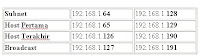
4. Bagaimana dengan alamat host dan broadcast yang valid? Kita langsung buat tabelnya. Sebagai catatan, host pertama adalah 1 angka setelah subnet, dan broadcast adalah 1 angka sebelum subnet berikutnya.

Kita sudah selesaikan subnetting untuk IP address Class C. Dan kita bisa melanjutkan lagi untuk subnet mask yang lain, dengan konsep dan teknik yang sama. Subnet mask yang bisa digunakan untuk subnetting class C adalah:


Subneting Pada IP Address Class B

Berikutnya kita akan mencoba melakukan subnetting untuk IP address class B. Pertama, subnet mask yang bisa digunakan untuk subnetting class B adalah:

Kita coba satu soal untuk Class B dengan network address 172.16.0.0/18.
Analisa: 172.16.0.0 berarti kelas B, dengan Subnet Mask /18 berarti 11111111.11111111.11000000.00000000 (255.255.192.0).


Penghitungan:

1. Jumlah Subnet = 2x - 2, dimana x adalah banyaknya binari 1 pada 2 oktet terakhir. Jadi Jumlah Subnet adalah 22-2 = 2 subnet
2. Jumlah Host per Subnet = 2y - 2, dimana y adalah adalah kebalikan dari x yaitu banyaknya binari 0 pada 2 oktet terakhir. Jadi jumlah host per subnet adalah 214 - 2 = 16.382 host
3. Blok Subnet = 256 - 192 = 64. Subnet berikutnya adalah 64 + 64 = 128. Jadi total subnetnya adalah 64, 128.
4. Alamat host dan broadcast yang valid?

Kita coba satu lagi untuk Class B.Bagaimana dengan network address 172.16.0.0/25.
Analisa: 172.16.0.0 berarti kelas B, dengan Subnet Mask /25 berarti 11111111.11111111.11111111.10000000 (255.255.255.128).


Penghitungan:

1. Jumlah Subnet = 29-2 = 510 subnet
2. Jumlah Host per Subnet = 27 - 2 = 126 host
3. Blok Subnet = 256 - 128 = 128
4. Alamat host dan broadcast yang valid?

Ok sebelum masuk ke Class A, coba ulangi lagi dari Class C, dan baca pelan-pelan


Subneting Pada IP Address Class A

Kalau sudah mantap dan paham, kita lanjut ke Class A. Konsepnya semua sama saja. Perbedaannya adalah di OKTET mana kita mainkan blok subnet. Kalau Class C di oktet ke 4 (terakhir), kelas B di Oktet 3 dan 4 (2 oktet terakhir), kalau Class A di oktet 2, 3 dan 4 (3 oktet terakhir). Kemudian subnet mask yang bisa digunakan untuk subnetting class A adalah semua subnet mask dari CIDR /8 sampai /30.
Kita coba latihan untuk network address 10.0.0.0/20.

Analisa: 10.0.0.0 berarti kelas A, dengan Subnet Mask /20 berarti 11111111.11111111.11110000.00000000 (255.255.240.0).

Penghitungan:

1. Jumlah Subnet = 212-2 = 4094 subnet
2. Jumlah Host per Subnet = 212 - 2 = 4094 host
3. Blok Subnet = 256 - 240 = 16
4. Alamat host dan broadcast yang valid?

Mudah-mudahan sudah setelah anda membaca paragraf terakhir ini, anda sudah memahami penghitungan subnetting dengan baik. Kalaupun belum paham juga, anda ulangi terus artikel ini pelan-pelan dari atas.

REFERENSI
http://romisatriawahono.net/

Share/Bookmark

Saturday

Konsep Subnetting

Cisco CCNASubnetting adalah termasuk materi yang banyak keluar di ujian CCNA dengan berbagai variasi soal. Juga menjadi momok bagi student atau instruktur yang sedang menyelesaikan kurikulum CCNA 1 program CNAP (Cisco Networking Academy Program). Untuk menjelaskan tentang subnetting, saya biasanya menggunakan beberapa ilustrasi dan analogi yang sudah kita kenal di sekitar kita. Artikel ini sengaja saya tulis untuk rekan-rekan yang sedang belajar jaringan, yang mempersiapkan diri mengikuti ujian CCNA, dan yang sedang mengikuti pelatihan CCNA 1.
Sebenarnya subnetting itu apa dan kenapa harus dilakukan? Pertanyaan ini bisa dijawab dengan analogi sebuah jalan. Jalan bernama Gatot Subroto terdiri dari beberapa rumah bernomor 01-08, dengan rumah nomor 08 adalah rumah Ketua RT yang memiliki tugas mengumumkan informasi apapun kepada seluruh rumah di wilayah Jl. Gatot Subroto.

Ketika rumah di wilayah itu makin banyak, tentu kemungkinan menimbulkan keruwetan dan kemacetan. Karena itulah kemudian diadakan pengaturan lagi, dibuat gang-gang, rumah yang masuk ke gang diberi nomor rumah baru, masing-masing gang ada Ketua RTnya sendiri-sendiri. Sehingga ini akan memecahkan kemacetan, efiesiensi dan optimalisasi transportasi, serta setiap gang memiliki previledge sendiri-sendiri dalam mengelola wilayahnya. Jadilah gambar wilayah baru seperti di bawah:

Konsep seperti inilah sebenarnya konsep subnetting itu. Disatu sisi ingin mempermudah pengelolaan, misalnya suatu kantor ingin membagi kerja menjadi 3 divisi dengan masing-masing divisi memiliki 15 komputer (host). Disisi lain juga untuk optimalisasi dan efisiensi kerja jaringan, karena jalur lalu lintas tidak terpusat di satu network besar, tapi terbagi ke beberapa ruas-ruas gang. Yang pertama analogi Jl Gatot Subroto dengan rumah disekitarnya dapat diterapkan untuk jaringan adalah seperti NETWORK ADDRESS (nama jalan) dan HOST ADDRESS (nomer rumah). Sedangkan Ketua RT diperankan oleh BROADCAST ADDRESS (192.168.1.255), yang bertugas mengirimkan message ke semua host yang ada di network tersebut.

Masih mengikuti analogi jalan diatas, kita terapkan ke subnetting jaringan adalah seperti gambar di bawah. Gang adalah SUBNET, masing-masing subnet memiliki HOST ADDRESS dan BROADCAST ADDRESS.

Terus apa itu SUBNET MASK? Subnetmask digunakan untuk membaca bagaimana kita membagi jalan dan gang, atau membagi network dan hostnya. Address mana saja yang berfungsi sebagai SUBNET, mana yang HOST dan mana yang BROADCAST. Semua itu bisa kita ketahui dari SUBNET MASKnya. Jl Gatot Subroto tanpa gang yang saya tampilkan di awal bisa dipahami sebagai menggunakan SUBNET MASK DEFAULT, atau dengan kata lain bisa disebut juga bahwa Network tersebut tidak memiliki subnet (Jalan tanpa Gang). SUBNET MASK DEFAULT ini untuk masing-masing Class IP Address adalah sbb:


Source : http://romisatriawahono.net/


Share/Bookmark

Wednesday

Cisco CCNA

cisco CCNAThe following notes were made while revising for my Cisco CCNA exam. They are not in any way a complete set of revision notes, but more like a last minute refresher for those bits of information that are important and need to be remembered.


If you find this page useful check out my other revision pages:
 Last minute revision guide
 Cisco IOS commands
 Layer 2 switching
 VLANS
 Spanning Tree Protocol - STP
 ISDN
 Novell IPX
 Access Control Lists - ACL
For other useful CCNA study guides, CCNA practice exams and technical training, see my certification and networking links page.
________________________________________

Cisco CCNA Certification Study Guide

 Ctrl+Shift+6 then X - Allows you to open more than one telnet session.
 Only the Hardware addresses change when packets go through routers.
 Half duplex Ethernet - One station can only send or receive at any time.
 Ethernet Frame - 64bytes Min 1518bytes Maximum.
 ISL frames are 1522bytes long, this can be mistaken for Giants and lost. Have to use ISL NIC cards. On router interface use 'encapsulation isl 2' to use ISL frames on VLAN 2.
 FX and SX are fibre media, 100VG-AnyLAN is twisted pair copper media.
 Spanning Tree is IEEE 802.1d - created by DEC (Digital Equipment Corp).
 BPDUs are Multicast frames, sent every 2 seconds. Blocked ports still receive BDPUs.
 Forward delay - Time taken from listening to learning (approx 50 seconds)
 Default IEEE bridge priority 32,768, used to select root bridge. If these are identical then switch with lowest MAC address is used.
 ISDN Protocols - E = Telephone network standards, I = Concepts, Terminology, Q = Switching, Signalling methods.
 ISDN Reference Points - R = non-ISDN device and TA, S/T = references point between NT1 and NT2, U = NT1 and ISDN network (US only)
 TE1 = Device compatible with ISDN, TE2 = Device NOT compatible with ISDN, TA = Converts non ISDN signals to ISDN signals, NT1 = Converts 4 wires into 2 wire local loop, NT2 = Providers equipment (Switch, PBX)
 BRI - 2 * B-channel 64kbps, 1 * D-channel 16kbps (D-channel - LAPD)
 PRI (Europe, Aus) - 30 * B-channel 64kbps, 1 * D-channel 64kbps (20.48Mbps)
 PRI (EUS, Japan) - 23 * B-channel 64kbps, 1 * D-channel 64kbps (1.544Mbps)
 ISDN supports IP, IPX, Appletalk...
 ISDN can use PPP, HDLC, LAPD, each B-channel needs a SPID
 Use static routes for ISDN otherwise it will keep link open.
 MAC address 48 bits (12 Hex), IPX address 80 bits.
 Netware 3.11 (1983-) - ethernet_802.3/novell-ether (Cisco default on Ethernet networks), Netware 3.12 or later (1985-) - Ethernet_802.2/sap - includes LLC, Ethernet_II - arpa, Ethernet_SNAP - snap, Netware 4.11 - use sap, Netware 5 uses IP
 Novell RIP - Metrics = ticks and hops (15 max), 60 sec updates (tick = 55ms / 1/18 sec)
 Novell 4.11 > uses NLSP (Netware Link Service Protocol) Link State Routing
 SAP - Updates 60 Secs - 4 = Netware file server, 7 = Print server, 24 = Remote bridge server
 Ping Responses - U = unreachable, C = congestion, I = user interrupt,? = unknown packet type, & = lifetime exceeded
 Trace Responses - N = Network unreachable, !H = Not forwarded due to ACL restriction, P = Protocol unreachable, U = Port could not be reached
 Ethernet 5-4-3 rule = Between 2 nodes there can only be max 5 segments, 4 repeaters and only 3 segments must have users.
 80/20 rule - 80% of traffic should be local 20% across backbone
 Class 1 repeater (translational) - delay 140 secs, number you can use 1
 Class 2 repeater (transparent) - delay 92 secs, number you can use 2
 CSMA/CD - Used on half duplex devices
 Auto-negotiate on FastEthernet checks link speed and duplex of line.
 Protocol field in IP header - TCP = 6, UDP = 17, ICMP = 1, IGRP = 9
 Ports - 20 FTP data, 21 FTP program, 23 - telnet, 25 - SMTP, 69 - TFTP, 53 - DNS, 80 - HTTP
 Loopback address - 127.0.0.1
 ACL - Standard ACL as close to destination as possible, Extended ACL as close to source as possible
 IP = 1-99, Ex IP = 100-199, AppleTalk = 600-699, IPX = 800-899, Ex IPX = 900-999, IPX SAP = 1000-1099
 Remember that there is an explicit ACL of 'deny all' if no statements match.
 Multiprotocol routing supports more than one routing protocol, allows a router to deliver packets from several routed protocols.
 Core Layer - High speed switching - free from filtering or anything which will slow packets etc.
 Distribution Layer - Packet manipulation, address area segregation, broadcast domains, VLANs, security (ROUTERS), WAN access, queuing, firewalls, multicast domains, ACLs
 Access Layer - End users, ACL/filters, remote access, shared bandwidth (SWITCHES), segmentation, DDR
 HSSI - 52Mbps max
 ATM cell size - 53bytes
 Cisco LMI - DLCI - 16-1007, ANSI LMI - DLCI 16-992 (DLCI = 10bits)
 LMI is a special DLCI = 1023
 LMI Multicasting reserved for 1019-1022
 LMI extensions - Virtual circuit status, multicasting, global addressing, simple flow control
 LMI types Cisco (default), ansi, q933a. From IOS 11.2 LMI is auto-sensed
 Class A - 1-126
 Class B - 128.1-191.255
 Class C 192.0.1-
 Class D - (1110 highest order bits) - remaining bits for multicasting
 Class E - (1111 highest order bits) - Reserved for future use
 RIP 1 (Classful), single subnet, periodic updates of full routing table, max hop count 15
 RIP 2 (Classless addressing), triggered updates, full routing table updates
 Directed Broadcast - All host bits set to 1 received by all hosts on local broadcast domain.
 Local Broadcast (255.255.255.255) - All bits set to 1 received by all hosts on local and remote broadcast domains.
 Synchronous serial links default to HDLC on Cisco routers
 VIP cards - type slot/port adapter/interface (e.g e/1/0/2) (remember first interface is 0 not 1)
 IGRP Metrics - Delay, Bandwidth
 Default route - ip route 0.0.0.0 0.0.0.0 172.16.20.1 - need to use 'ip classless' (Classless is enabled by default on IOS 12.x) (Only work on stub networks)
 ip default-network 172.16.1.0
 CDP timer default 90 secs, holdtime 240 secs
 Trunked links - FastEthernet or GigabitEthernet only
 Frame Tagging - ISL = Adds it's own FCS, Cisco propriety (default), IEEE 802.1q
 LAN Emulation (LANE) - Used for multiple VLANS over ATM
 802.10 - FDDI Frame Tagging
 Hosts can only communicate between VLANS using Layer 3 devices
 VTP Modes - Server (Default for Catalyst switches) Need at least one server in a VTP domain. All changes are advertised. Client - Sends and receives updates. To make a switch a server make it a client first then promote it once it's VTP database has received the latest revision. Transparent - Does not participate in VTP domain, but forwards VTP ads through trunked links. They keep their own database.
 VTP adverts sent every 5 mins or when a change occurs, changes only kept by other switches if higher rev no than their current version.
 VTP pruning - If a switch does not have any ports configured for VLAN 5 then it won't receive updates for it. Disabled by default. Enabled across entire domain if configured. VLAN 1 is not pruning eligible.
 Config Reg - 00 Rom Monitor, 01 Boot Image from ROM, 02-F NVRAM, Bit 6 set to 1 to ignore NVRAM. Register is 16 Bits.
 1900 Switch Config - enable password level 1 - usermode, level 15 - enable password.
 1900 switch can have up to 64 VLANS. You cannot telnet from a switch but you can telnet into it.


Administrative Distances
Routing Protocol Administrative Distance
Connected Intf 0
OSPF 110
Static route 1
RIP 120
EIGRP 90
UNKNOWN 255
IGRP 100

• RIP - Updates 30 secs, Max Hops 15, Invalid 90 secs, Flush 240 secs, metrics hops, load balance 6 equal cost links
• IGRP - Updates 90 secs, max hops 255 (default 100), invalid 3x90 secs, holddown 3x90+10 secs, flush 7x90 secs, metrics bandwidth, delay, load balance upto 6 unequal cost links.
• When routers are converging no data is sent.
• Frame Relay - 64 kbps - 1.544 Mbps, non-broadcast multi-access encapsulation (NBMA), dynamic bandwidth allocation, congestion control. Can use PVC and SVCs, PVC more common. Virtual circuit established before data sent. Encapsulation Cisco (Default), IETF (use when connecting non-cisco routers). Static routes are more stable than IARP.
• Routers are DTE devices by default, DCE interfaces need a clock rate.
• Telneting uses layers 1-4 so a good test of functionality. If you type a command the router doesn't know or type and IP address it will try to resolve the name and telnet.
• Bandwidth command sets cost for serial links. This is only used by routing protocols so they can 'cost' paths. Default = 1.544kbps (T1) Command is in Kbps.
• Clock rate command is in bps.
• HDLC - Connection-orientated, operates at the datalink layer, small overhead, no way of distinguishing network protocols. Every vendors implementation is different, NO authentication, CISCO Default over serial lines.
• LAPB - Connection-orientated, datalink layer protocol, HUGE overhead, uses windowing, used instead of HDLC for error prone links.
• PPP - industry standard, used when connection between different vendors devices. NCP to identify network protocol, authentication, compatible with async + sync links, operates at physical + datalink layers only. PAP - insecure authentication, CHAP auth provides initial + periodic auth. PPP compression uses stacker and predictor methods. Error detection - PPP uses quality and magic number methods. Multilink - IOS 11.1 only, spreads the load over 2 parallel circuits (bundle).
• Ethernet 0 is up, line protocol is down - keepalive or framing issue, check keepalives on both sides should match, check clocking on DCE, check encapsulation on both ends.
• Ethernet 0 is down, protocol is down, - carrier detect is not present, other end maybe administratively shutdown or interface or cable problem.
• Ethernet 0 is administratively shutdown - the 'no shutdown' command has not been issued on the interface.
• Show interface serial 0 - shows bandwidth, MTU, keepalives.
• MTU default = 1500bytes.
• Bandwidth default = 1.544Kbps (T1)
• Keepalives default = 10 seconds.
• Use a cross over cable to connect devices of the same type (e.g router Ethernet intf to router Ethernet intf)
• Cross over cables swap pins 1 and 3 RD, and pins 2 and 6 TX
• STP - 10-100Mbps - 100metres
• ScTP - 10-100Mbps - 100metres
• UTP - 10-100Mbps - 100metres
• Coax - Coaxial - 500metres
• Fiber - Single Mode upto 3000metres
• Fiber - Multimode upto 2000metres
• Connectionless protocols rely on application layer protocols for error handling and delivery.
• EIGRP holds separate routing tables for IP,IPX,Appletalk, but only uses one protocol to distribute the updates.
• CDP uses SNAP (Subnetwork Access Protocol) to enable neighbouring devices to exchange data.
• IPX NLSP - link-state routing protocol intended to replace IPX RIP and SAP
• NCP - Netware Core Protocol - Provides clients with access to server resources
• IPX SAP - Sent every 60 seconds - includes all known services.
• sap is Cisco default for Token Ring networks, SNAP is default for FDDI networks
• VTP allows VLANs to be trunked over Ethernet, ATM, LANE or FDDI
• Gigabit Ethernet using Multimode Fibre can run up to 260m
• 100BaseFX up to 400m
• VLAN Management Policy Server - Must be configured with all hosts' MAC addresses for dynamic allocation.
• Standard ping - 5*100 byte ICMP echos, time out 2 seconds
• DHCP uses UDP packets
• Passive interface command stops interface sending routing updates, but still receives them.
• 2 ways to configure VLAN membership, statically or dynamically through VLAN Management Policy Server.
• ISL and Trunk protocol used to configure trunking on a switch.
• Pre 10.3 IOS commands Config Net - copy config from tftp to DRAM Config Mem - copy NVRAM to DRAM
• IP routing table [administrative distance/composite metric]
• IPX routing table [ticks/hops]


CISCO IOS REVISION COMMANDS
________________________________________

SHOW COMMANDS - CISCO ROUTERS
Show version - software version, config files, boot images, config register, basic config of router
Show ipx interface - status, ipx rip and sap received/sent, ipx access-lists
Show ipx route - ipx routing table
Show ipx servers - server list (name, port, hops, type of service)
Show ipx traffic - number/type of packets, RIP and SAP packets
Show protocol - ipx addresses of an interface, IP addresses and routing protocol
Show ip protocol - routing update times, networks active on, neighbour routers, administrative distances, AS number
Show access-lists - shows standard and extended access-lists on all interfaces
Show access-list 101
Show ip interface - IP addresses, masks, MTU, access-lists, split horizon, ICMP, CDP status, NAT statistics, LMI info, DLCIs
Show interface serial 0 - shows bandwidth, MTU, keepalives
Show ip route - ip routing table
Show cdp neighbor - deviceID, local intf, holdtime, capability, platform, remote portID
Show cdp entry * - IP address of neighbour, protocol info, platform, capability, portID, holdtime, same info as show version, neighbour device ID, local interface
Show cdp neighbor detail - same as above also IP address, version info
Show cdp traffic - info on traffic and errors
Show cdp interface - encapsulation, timer, holdtime for each intf
Show controllers serial 0 - shows DTE/DCE connections, buffer size, collisions, mac address
Show host(s) - shows hostname to IP resolution of hosts
Show session(s) - shows connections to a remote device
Show users - shows connections to your router, port and time connected
Show frame-relay lmi - lmi errors and lmi type
Show frame-relay pvc - all configured PVC's, DLCI numbers, status of connections, No. of BECN/FECN
Show frame-relay pvc 16
Show frame-relay map - ip to dlci mappings
Show run - display router config (RAM), configured PVCs, ACLs.


SHOW COMMANDS - 1900 SWITCH
Show mac-address-table
Show run
Show ip - like ipconfig
Show port system - shows switching method
Show vtp
Show trunk A allowed-vlans - shows which VLANS allowed on trunk link
Show vlan-membership
Show vlan 2
Show vlan - verify VLAN config
Show history - shows last 10 commands entered by default
Show terminal - shows terminal config + history buffer size


GENERAL ROUTER COMMANDS
Banner exec - for activation or incoming vty
Banner incoming - displayed on reverse telnet sessions
Banner login - displayed on all connected terminals. Displayed before MOTD banner but before login prompts
Bfe - manual emergency mode setting
Clear counters - clears counters on all interfaces
Clear frame-relay-inarp - clears dynamic mappings
Clear line 1 - clears vty 1 connection to a remote router
Clock set 10.30.10 28 may 2002
Config-register 0x2102 - changes config register
Copy flash tftp
Copy tftp flash - copies IOS image from tftp server default directory to router flash
Disable - to get back to user mode from privileged
Disconnect 1 - clears a connection to a remote router
Enable - to get into privileged mode
Enable last-resort - define enable action if no tacas servers respond
Enable use-tacas - tells the router to authenticate passwords through a tacas server
Encapsulation isl 3 - encapsulates ISL frame-tagging for VLAN 3 on an interface
Exec timeout 0 1 - sets console timeout to 1 second
Exec-timeout 0 0 - sets exec timeout to never timeout
Exec-timeout 1 0 - set exec timeout to 1 minute
Ip domain-lookup - enables DNS (use no form to stop this)
Ip domain-name nikmakris.com - appends domain name to hostname (required for DNS)
Ip host nik 172.17.1.63 - adds to host table (up to 8 ip addr)
Ip name-server - sets ip address(es) of DNS servers
Lock - locks the terminal
Logging synchronous - stops console messages overwriting commands
Logout - to logout of the router
Media-type 100BaseX - sets media type
Mrinfo - request neigbour and version information from a multicast router
No login - sets line, vty ports not to prompt for login info
Passive-inteface s0 - disables routing updates on interface (Global command) - they are not sent out this interface but they are still received.
Ping ipx 40.0000.0c8d.5c9d
Service password-encryption - encrypts passwords (Global command)
Terminal monitor - needed to view debug commands from telnet session
Terminal history size 50 - sets command history to 50 lines
Tftp-server system - Make router a tftp server


CONFIGURE COMMANDS
Interface Ethernet 2/0/1 - type slot / port adapter / port number (interface) for VIP cards
Config terminal - configures RAM
Config network (config net) - changes a config on a tftp host
Config memory - configure NVRAM
Ip address 172.17.1.63 255.255.255.0 secondary - adds a secondary subnet address to an interface
Clock rate 56000 - sets clock rate to 56kbps for DCE interfaces


ACCESS LISTS (ACL)
Access-enable - creates a temporary access-list entry
Access-template - creates a temporary access-list entry
Access-profile - apply user profile to interface

Access-list 1 permit 0.0.0.0 255.255.255.255 - same as next line
Access-list 1 permit any - permits any host
Access-list 1 permit 172.30.16.29 0.0.0.0 - same as next line
Access-list 1 permit host 172.30.16.29 - permits host 172.30.16.29
No access list 1 - deletes access list 1
Ip access-group 1 out (out is default)
Access-list 101 deny tcp 172.16.4.0 0.0.0.255 any eq telnet
Access-list 101 permit ip any any established (TCP connection)
Router(Config)#ip access-list standard nik
Router(Config std-nacl)#deny any log (log - logs packets)

No ip access-group in - won't delete inbound lists if you leave the in off the end of the command


FRAME RELAY
Router(Config)#int s0
Router(Config-if)#encapsulation frame-relay cisco (default)
Router(Config-if)#exit
Router(Config)#int s0.16 point-to-point
Router(Config-if)#no inverse-arp
Router(Config-if)#ip address 172.17.1.63 255.255.255.0
Router(Config-if)#bandwidth 64 - sets bandwidth to 64kbps (Only used by routing protocols)
Router(Config-if)#frame-relay map ip 172.16.30.17 16 ietf broadcast - broadcast tells the router to send broadcasts out this intf


IGRP CONFIGURATION
Router(Config)#router igrp 50
Router(Config-router)#timers basic 15 45 0 60
Router(Config-router)#variance 1-128 (controls load balancing between best and worse metrics)
Router(Config-router)#traffic-share balanced/min
Balanced - share inversely proportional to metrics
Min - use routers that have only min costs
Router(Config-router)#network 128.6.0.0
Router(Config-router)#no metric holddown
Router(Config-router)#metric maximum-hop 50


IPX RIP CONFIGURATION
Router(Config)#ipx routing - enables IPX routing, RIP and SAP
Router(Config)#ipx maximum-paths 2 - enables equal cost load balancing over 2 paths
Router(Config)#ipx per-host-load-share - ensures all packets to 1 destination are sent over same line
Router(Config)#int e0
Router(Config-if)#ipx network 10 encapsulation sap secondary - assigns ipx network 10 to a secondary interface on Ethernet 0 with encapsulation Ethernet_802.2
Router(Config-if)#ipx delay 6 - sets tick metric for IPX RIP (LAN = 1, WAN = 6 default)
Router(Config-if)#exit


CISCO ISDN CONFIGURATION
Router(Config)#interface bri 0
Router(Config-if)#ip address 172.17.1.63 255.255.255.0
Router(Config-if)#no shutdown
Router(Config-if)#dialer-group 1
Router(Config-if)#dialer map ip 172.16.60.2 name 8042 8350661
(Next router ip - hostname of next route (auth) - number to dial)
Router(Config-if)#dialer load-threshold 2 either - makes both interfaces come up immediately
Router(Config-if)#dialer load-threshold 255 either - only brings up 2nd B-channel if first is 100% loaded
Router(Config-if)#hold-queue 75 in - holds 75 packets in the queue during connection
Router(Config-if)#dialer idle-timeout 300 - sets idle time out (120 default)
Router(Config-if)#encapsulation ppp
Router(Config-if)#exit
Router(Config)#dialer-list 1 list 110
Router(Config)#access-list 110 permit tcp any any eq smtp
Router(Config)#access-list 110 permit tcp any any eq telnet


STATIC/DEFAULT ROUTES
Ip route 0.0.0.0 0.0.0.0 172.16.20.1 = default route
Ip default-network 172.16.1.0
Ip route 172.17.1.63 255.255.255.0 serial 1 1 permanent - keeps static route even if router cannot communicate with it, administration distance 1


CISCO DISCOVERY PROTOCOL (CDP) COMMANDS
Cdp timer 90
Cdp holdtime 240
Cdp enable (no cdp enable)


1900 SWITCH CONFIGURATION
#config t
(Config)#enable password level 1 nikolas - usermode password
(Config)#enable password level 15 makris - enable password
(Config)#enable secret nik2 - precedes the enable p/w
(Config)#hostname nik
(Config)#vtp pruning enable - enables pruning on whole switch
(Config)#delete vtp - deletes VTP database
(Config)#vtp server (client/transparent)
(Config)#vtp domain nikolas
(Config)#vtp password cisco
(Config)#ip address 172.17.1.63 255.255.255.0
(Config)#ip default-gateway 172.17.1.50
(Config)#switching-mode store-and-forward (fragment-free)
(Config)#vlan 2 name sales
(Config)#vlan 3 name marketing
(Config)#int Ethernet 0/1 - slot 0/port 1
(Config-if)#vlan-membership static 2
(Config-if)#description Finance_VLAN
(Config-if)#port secure max-mac-count 1 - allows only one mac address per port
(Config-if)#exit
(Config)#int f0/26
(Config-if)#trunk on - enables trunking of all VLANS not just VLAN 1
(Config-if)#no trunk-vlan 3 - stops trunking vlan 3
(Config-if)#duplex full - sets to full duplex (auto sense default)
(Config-if)#exit
(Config)#copy tftp://192.168.0.120/cat1900EN_9_00.bin opcode - download into flash memory
(Config)#copy nvram tftp://192.168.0.120/cat1900EN
(Config)#copy tftp://192.168.0.120/cat1900EN nvram
(Config)#delete nvram - deletes config
(Config)#delete vtp - deletes VTP database
(Config)#clear mac-address-table [dynamic]


CISCO DEBUG COMMANDS
Debug ipx routing activity - info on RIP updates
Debug ipx sap - info on sap updates
Debug ip igrp events - what's being rec'd sent, route type (int/ext,system), source, dest
Debug ip igrp transactions - shows contents of routing updates
Debug ip rip - source/contents of updates, network, metrics
Debug frame-relay lmi - enables verification of connection
Debug ppp authentication
UNDEBUG ALL


CISCO CCNA - LAYER 2 SWITCHING
________________________________________

Layer 2 Switching
 Switches use Application-Specific-Integrated Circuits (ASIC's) to build and maintain filter tables.
 Switching provides:
 Hardware-based bridging
 Wire speed
 Low latency
 Low cost
 Layer 2 switching breaks up collision domains making a flatter network than an ordinary 10BaseT network.
 Cisco 80/20 rule - Make sure users spend 80% of their time on the local segment.
 Broadcasts, multicasts and slow converging spanning tree limits the size of a switched network.
 Bridges are software based (slower) compared to switches which are hardware based.
 Bridges can only have one Spanning Tree instance per bridge.
 Bridges can only have up to 16 ports.
 Trashing the MAC table - Occurs when there is a loop in a switched network and the MAC filter table is being constantly updated.
 Ethernet is half duplex - Only one station can send or receive at any one time.
 Full duplex Ethernet allows transmission and reception at the same time. Two pairs of wires, full duplex NIC cards and a switched connection are required.
 Switches segment collision domains but forward broadcast packets to all ports.
 Ethernet 5-4-3 rule - Between any 2 nodes there can only be a maximum of 5 segments, 4 repeaters and only 3 of those segments can have hosts.

Switch Memory Buffering - 2 Types (Port Based and Shared Memory)
 Port Based can cause problems holding up transmission of all other packets if there is a delay on one port.
 Shared Memory Buffering is not linked to a specific port but dynamically allocated within a shared pool of memory.

Switching Methods
 Store and Forward - Entire frame is received before forwarding is commenced. Error detection is high, latency low.
 Cut through - Comes in 2 types (Fast Forward and Fragment Free).
1. Fast Forward - Forwards frame after receiving destination address, error prone.
2. Fragment Free - Filters out collision packets (If packet data > 64bytes ok)
 Ethernet frame maximum size = 1518bytes (All of this is received before forwarding by Store and Forward)
 Ethernet frame minimum size = 64 bytes (Only this much of packet read by Fragment Free)

Repeaters - 100BASE-T LANs
Type Max delay Max number you can use
Class 1 repeater (Translational) 140 1
Class 2 repeater (Transparent) 92 2


CISCO CCNA - VLANS
________________________________________

VLANS
 Increase security and ease administration and relocation.
 Break up broadcast domains.
 VLANS work at layer 2 and 3 of OSI model.
 Communication between VLANs uses layer 3 routing.
3 ways of assigning a switched port to VLANs:
 Port-Centric - All nodes connected to ports in the same VLAN are assigned to the same VLAN ID.
 Static VLANs - Statically assign ports to a VLAN.
 Dynamic VLANs - Ports that can automatically determine their VLAN assignments based on MAC addresses.
 Switches segment LANs into individual collision domains, VLANs break up broadcast domains as well.

VLANS and Frame Tagging
Access Link - Only part of one VLAN (native VLAN of the port), any devices attached to an access link are unaware of VLAN membership.
Trunk Links - Trunks can carry multiple VLANS. Supported on fast or gigabit links only. Used to transport VLANS between devices.
Frame Tagging and Frame Tagging formats:
 ISL (Inter-Switch Link) is Cisco's Proprietary frame tagging format.
 IEEE 802.1q IEEE standard.
 ISL - 26 bytes long + 4 bit FCS (frame check sequence)
 ISL only used on fast and gigabit Ethernet.
 802.1q - Use IEEE standard if you are trunking between non-Cisco switches. Since IEEE frame tagging actually inserts a field in the frame.
 LANE (LAN Emulation) - Used to communicate multiple VLANS over ATM.
 802.10 (FDDI) - VLAN communication over FDDI, uses SAID field in frame (Cisco Proprietary)
 Frames with ISL frame tagging are over the maximum length specified by the Ethernet standard, these will be recorded as giants if frame tagging is not enabled. Maximum Ethernet frame is 1518 bytes, ISL tagged frames can be up to 1522 bytes long.
 ISL NIC cards are available for servers.
 ISL information is only added to frames that are forwarded out of configured trunk links.
 ISL information is removed if it is forwarded out an access link.
 Trunking makes a single port able to be part of multiple VLANS.
 Non trunked links between switches forward VLAN1 information only.
 Dynamic Trunking Protocol (DTP) - Manages trunk negation.
 Communication between VLANS requires layer 3 devices (Routers)
 Cisco 1600, 1700, 2500 do not support ISL.

VTP - VLAN Trunk Protocol
 VTP manages all configured VLANS across a switched network. VTP provides:
 Tracking and monitoring of VLANS.
 Consistent VLAN configuration across all switches.
 VLANS to be trunked across mixed networks.
 Reporting of new VLANS.
 Plug and Play VLAN configuration.
 VTP is not needed if you only have 1 VLAN.
 VTP advertisements sent every 5 minutes or when a change occurs. Switches only overwrite information with a higher revision number.

VTP Modes of Operation
Server (Default for Catalyst switch) - You need at least one server in a VTP domain. All changes are advertised in VTP domain.
Client - Receives info from VTP servers. Sends and receives updates but cannot make changes. To promote a switch to a server make it a client first, to receive all VTP info, then promote it to a server.
Transparent - Does not participate in a VTP domain, but forwards VTP advertisements through trunked links. Transparent switches keep their own database so you can add or delete VLANS from it (Locally significant).

VTP Pruning
Reduces bandwidth, by reducing broadcasts, multicasts etc that are unnecessary. If a switch does not have any ports configured for VLAN 5 then it will not receive the VTP update.
 VTP Pruning is disabled by default on all switches.
 When VTP Pruning is enabled it is enabled across the entire domain.
 Only VLANs 2-1005 are pruning-eligible.
 VLAN1 is an administrative VLAN.


CISCO CCNA - SPANNING TREE PROTOCOL - 802.1d - Algorithm by Radia Perlman
________________________________________

Spanning Tree Protocol
The Spanning Tree Protocol was created by DEC (Digital Equipment Corporation) now Compaq. This is not compatible with the IEEE 802.1d version which Cisco use.
The Spanning Tree Protocol:
 Prevents loops, loops cause broadcast storms
 Allows redundant links
 Resilient to topology changes
 STA (Spanning Tree Algorithm) - Used to calculate loop-free path
 BPDUs (Bridge Protocol Data Units) are sent and received by switches in the network every 2 seconds (default) to determine spanning tree topology.
Bridge Priority - Numerical value held by switches. All Catalyst switches are 32768
Bridge ID = MAC Address

Spanning Tree States
Blocking No frames forwarded, BPDUs heard
Listening No frames forwarded, listening for frames
Learning No frames forwarded, learning addresses
Forwarding Frames forwarded, learning addresses
Disabled No frames forwarded, no BPDUs heard

STA - Spanning Tree Algorithm
Spanning Tree Algorithm is used to calculate a loop-free path.
All switch ports are in blocking mode to begin with. It takes approx 30 seconds until packets can be forwarded.
Step 1 : Elect Root Bridge - Lowest bridge priority, if there is a tie then switch with lowest bridge ID
Step 2 : Elect Root Ports - Locate redundant paths to root bridge; block all but on root. Root Path Cost is cumulative cost of path to root bridge. Ports directly connected to Root Bridge will be root ports, otherwise lowest root path cost used.
Step 3 : Elect Designated Ports - Single port that sends and receives traffic from a switch to and from Root Bridge - Lowest cost path to Root Bridge.

Spanning Tree Overview
 There can only be one Root Bridge.
 Root-Bridge ports are called 'Designated' and are set to send and receive traffic (forwarding state). All other redundant links to the root bridge are shutdown.
 Blocked ports still receive BPDUs.
 Convergence occurs when switches have transitioned to either forwarding or blocking states. No other data is forwarded during this time.
 Forward delay - Time taken for a switch to go from Listening to Learning (50 seconds default).
 IEEE default priority = 32,768, this is true for all devices running STP IEEE version.
 Port Fast Mode - Immediately brings a port from blocking to forwarding state by eliminating forward delays.
 Bridges can only have one spanning tree instance compared to switches which can have many.
 Bridge Protocol Data Units send confirmation messages using multicast frames.


CISCO CCNA - ISDN - Integrated services Digital Network
________________________________________

ISDN - Integrated services Digital Network
 Carries a variety of traffic. Video, Circuit Switched Data And Telephone Services using normal phone network.
 Call set up and data rates faster than modem.
 Operates at layer 1 to 3.
 ISDN uses SS7 signalling to set up a path with a remote switch.

ISDN Physical layer
 ISDN frames differ depending on inbound (network to terminal NT format) or outbound (terminal to network TE format).
 ISDN frames are 24 bits long.
 ISDN BRI service offers 2 B channels operating at 64kbps which can be used independently from one another for user data or voice traffic.
2*(2*8B + 2D + 6F) sent in pairs
ISDN BRI sent at 8000/sec
(1*8B + 2D + 6F) = 24*8000 = 192kbps
but effective data rate = 2*8B = 16*8000 = 128kbps

ISDN Data link layer
 ISDN datalink layer is LAPD - Link Access Procedure D channel - ensures control and signalling information flows properly.
 D channel operates at 16kbps and is used to carry control and signalling information.
 Terminals cannot transmit into D channel unless they first detect a specific number of ones (indicating no signal). If the TE detects a bit in the echo (E) channel that is different from it's D bits then it stops transmitting immediately.

ISDN SPIDs - Service Profile Identifiers
You also need to know your assigned SPID to identify your configuration at the CO.
 SPIDs allow multiple ISDN devices to share local loop.
 SPIDs are processed during each call set up.
 SPIDs assigned by your service provider.
 A SPID is required for each B channel.

ISDN Devices
TE1 - Device compatible with ISDN network, connects to NT1 or NT2
TE2 - Device not compatible with ISDN requires TA
TA - (terminal Adapter) Converts signals so non-ISDN devices can use ISDN
NT1 - Connects 4-wire ISDN to 2-wire local loop
NT2 - Directs traffic to and from different subscriber devices and NT1

ISDN Reference Points
R - References points between non-ISDN device and TA
S - References points that connect into NT2 (Inbound)
T - References Outbound connections from NT2 into ISDN network or NT1
U - References connection between NT1 and ISDN network (North America only)

ISDN Protocols
E - Telephone network standards
I - Concepts, terminology, general methods
Q - How switching should operate

Dial on Demand Routing - DDR
Before setting up a dial on demand connection you must consider what kind of traffic will initiate the dial up connection, consider the following points:
 You must first establish how ISDN connections will be initiated, established and maintained.
 You must establish which sites are involved, who can initiate and terminate connections.
 Applications supported over DDR, which applications can initiate a connection.
 What unexpected protocols could cause a connection to be made.

ISDN switch types
For proper ISDN configuration you have to configure the correct switch type. Most common type in US is At&T's 5ESS and Nortel DMS-100. In UK it's Net3 and Net5.


Novell Internet Packet Exchange (IPX)
________________________________________

Novell IPX
 IPX is a connectionless layer 3 protocol like IP. An IPX address is made up of 32 bits network and 48 bits MAC address (80 bits in total). It is important you know the length of these in binary and hexadecimal.
 SPX (Sequenced Packet Exchange) is a connection-orientated layer 4 protocol similar to TCP.
 NCP (Netware Core Protocol) - Client server connections and applications communication.
 SAP (Service Advertising Protocol) - Advertises network services.
 NLSP (Netware Link Services Protocol) - Link state routing protocol.
 GNS (Get Nearest Server) - A type of SAP advertisement used to locate a server for client log-in.
Netware 2 - 3.11 (1983-1985)
Ethernet_802.3 (default encapsulation on Cisco routers) Cisco name novell-ether. Also called Ethernet raw.
Netware 3.12 - 4.x (1985 - )
Ethernet_802.2 Cisco name sap (service access points) This is standard IEEE format and includes LLC header.
Ethernet_II
Ethernet_II uses TCP/IP Cisco name arpa. Novell 5.0 onwards uses TCP/IP instead of IPX.
Ethernet_SNAP
Cisco name snap (Subnetwork Access Protocol)

Default Encapulations
 Ethernet - novell-ether
 Token Ring - sap
 FDDI - snap

Novell IPX RIP
 Incompatible with IP RIP.
 2 Metrics used (Hops, Ticks).
 Max hop count 15.
 Updates every 60 sec.
 Not efficient for large networks

IPX and Cisco routers
 Cisco routers maintain routing tables for each IPX protocol enabled on the network.
 Routers can provide network-based LAN sharing on IPX server-less LAN segments.
 Each network address must use a distinct IPX encapsulation.
 Subinterfaces on routers are used to assign multiple network numbers and encapsulations on single interfaces.

IPX IOS Router Configuration
Router(config)# ipx routing
Router(config)# ipx maximum paths x (default 1, max 512)
Router(config)# int e0.1
Router(config-if)# encapsulation novell-ether
Router(config-if)# ipx network 9e
ipx delay - used to manually set the tick metric delay on an interface. Default values for interface delays are LAN = 1 tick, WAN = 6 ticks.

Router IPX Troubleshooting
Show ipx interface - status / parameters (IPX RIP and SAP info)
Show ipx route - routing table
Show ipx servers - server list)
Show ipx traffic - number / type of packets
Show protocol - IPX address of an interface
Debug ipx routing activity - info on RIP updates
Debug ipx sap - info on Sap updates
Ping

SAP Service Advertising Protocols
 4 - Netware File Server
 7 - Print Server
 24 - Remote bridge server (router)

 SAP packets sent every 60 seconds.
 Routers build SAP tables.
 Routers only respond to GNS requests when servers are not local.


CISCO ACCESS CONTROL LISTS REVISION
________________________________________

ACCESS CONTROL LISTS (ACL)
Access Control Lists are used to:
 Prioritise traffic
 Restrict or reduce updates
 Provide basic security
 Block types of traffic

Access control list placement
 Standard ACLs - Place as close to destination as possible.
 Extended ACLs - Place as close to source of traffic as possible.
 Only one ACL per port per direction is allowed.
 ACL are more efficient on outbound port.
 If a packet does not match the ACL statement then it will be implicitly denied.
 Once a packet matches an ACL statement no other checks are made, it is permitted.

ACL IOS COMMANDS
Standard ACLs - Used to permit or deny an entire protocol suite.
The following two statements have the same effect:
Router(config)# access-list 1 permit 0.0.0.0 255.255.255.255
Router(config)# access-list 1 permit any
The following two statements also have the same effect:
Router(config)# access-list 1 permit 172.30.16.29 0.0.0.0
Router(config)# access-list 1 permit host 172.30.16.29

Extended ACLs - Used to permit or deny specific protocols
Protocol ranges are used in ACL statements to deny specific protocols. Below are the ones you will need for your CCNA.

Protocol Range
IP 1-99
Extended IP 100-199
Appletalk 600-699
IPX 800-899
Extended IPX 900-999
IPX SAP 1000-1099

Use the following table to permit or deny specific protocols, ports or ranges of port numbers, an example ACL follows.

lt Less than
gt Greater than
neq Not equal to
eq Equal to

Router(config)# access-list 101 deny tcp 172.16.4.0 0.0.255.255 any eq 23
Router(config)# access-list 101 permit ip any any established - Established keyword used to connect with a TCP established connection.

Named ACLs
Named access control lists are another way of creating ACLs, any example follows.
Router(config)# ip access-list standard Nik
Router(config std-nacl)# deny any log - used to deny log packets.

Viewing ACLs
Router(config)# show access-lists - shows all access lists.
Router(config)# show access-list 101 - shows access list 101.
Router(config)# show ip interface - used to find out which access lists are on which interfaces.

Configuring ACLs on an interface
Router(config)# interface s1
Router(config-if)# ip access-group 1 out /in - out bound is the default.

Removal of ACLs
Router(config)# no access-list 1


NOVELL IPX: INTERNETWORK PACKET EXCHANGE PROTOCOL

Internetwork Packet Exchange (IPX) is a legacy network protocol used by the Novell NetWare operating systems to route packets through an internetwork. IPX is a datagram protocol used for connectionless communications - similar to IP (Internet Protocol) in the TCP/IP suite. Higher-level protocols, such as SPX and NCP, are used for additional error recovery services.
To make best-path routing decisions, IPX uses the services of a dynamic distance vector routing protocol such as Routing Information Protocol [RIP ]) or NetWare Link-State Protocol [NLSP]).
Novell IPX network addresses are unique and are represented in hexadecimal format that consist of two parts: a network number and a node number. The IPX network number, which is assigned by the network administrator, is 32 bits long. The node number, which usually is the Media Access Control (MAC) address for one of the system's network interface cards (NICs), is 48 bits long. IPX's use of a MAC address for the node number enables the system to send nodes to predict what MAC address to use on a data link.

Novell NetWare IPX supports four encapsulation schemes on a single router interface:
• Novell Proprietary- Also called 802.3 raw or Novell Ethernet_802.3, Novell proprietary serves as the initial encapsulation scheme that Novell uses.
• 802.3- Also called Novell_802.2, 802.3 is the standard IEEE 802.3 frame format.

• Ethernet version 2- Also called Ethernet-II or ARPA, Ethernet version 2 includes the standard Ethernet Version 2 header, which consists of Destination and Source Address fields followed by an EtherType field.
• SNAP- Also called Ethernet_SNAP, SNAP extends the IEEE 802.2 header by providing a type code similar to that defined in the Ethernet version 2 specification.
The maximum length of the data section of an IPX packet varies from a minimum of 30 bytes (the header only) depending on the lower layer MAC protocol (Ethernet or token ring) that is being used.


TCP/IP Quick Guide: A comprehensive pocket and quick reference for people who are learning and using TCP/IP.

Networking 2006 - A Calendar exclusively designed for IT/Networking Pros.


Protocol Structure - Novell IPX: Internetwork Packet Exchange Packet Header

The NetWare IPX Packet Header:
8 16bit
Checksum
Packet Length
Transport control Packet Type
Destination Network (4 bytes)
Destination node (6 bytes)
Destination socket (2 bytes)
Source network (4 bytes)
Source node (6 bytes)
Source socket (2 bytes)

• Checksum- Indicates that the checksum is not used when this 16-bit field is set to 1s (FFFF).
• Packet length- Specifies the length, in bytes, of a complete IPX datagram. IPX packets can be any length, up to the media maximum transmission unit (MTU) size (no packet fragmentation allowed).
• Transport control- Indicates the number of routers through which the packet has passed. When this value reaches 16, the packet is discarded under the assumption that a routing loop might be occurring.
• Packet type- Specifies which upper-layer protocol should receive the packet's information. It has two common values:
o 5- Specifies Sequenced Packet Exchange (SPX)
o 17- Specifies NetWare Core Protocol (NCP)
• Destination network, Destination node, and Destination socket- Specify destination information.
• Source network, Source node, and Source socket- Specify source information.


Related Protocols
IP , IPv6 , NetWare , SPX , RIP , NLSP

Sponsor Source
IPX is a Novell protocol.


Reference
http://www.novell.com/: IPX Structure
http://www.cisco.com/univercd/cc/td/doc/cisintwk/ito_doc/netwarep.htm : NetWare Protocols


Share/Bookmark
Link To Your Site